• November 8, 2022

How-To Increase Linear Motor Efficiency With Increased Phase Counts

Understanding Electric Motor Efficiency and Phase Counts

Introduction

A little over 200 years ago, we first learned how to create magnetic fields using electricity. Today this concept is used broadly in electric motors across many industries. With such relatively little time spent innovating this invisible and non-intuitive phenomenon, it’s no wonder that improvements to efficiency are still being found. This paper focuses on an optimization of the commonly used Permanent Magnet Brushless DC motor (PMDC). These electromagnetic linear motors have become widely popular due to their efficiency and high force densities.

Efficiency improvements to PMDC motors are welcome as energy costs rise and applications like electric cars and factory automation strive to do more with less. The optimization discussed finds improvements to efficiency and of the smart electric linear motors by changing the way they are both constructed and driven.

For simplicity the discussion here will relate to linear motors and, to avoid some nonlinearities and other complications, this discussion will focus on ‘air-core’ motors, or those not using iron within the stator. With that said, the concepts here reach beyond the simplified examples – for instance to rotary motors, and motors with an iron-core.

A linear DC motor render with internal components exposed.
A Linear Permanent Magnet Brushless DC Motor

Background

PLEASE NOTE: To readers with experience in the anatomy of PMDC motors, this section might not be required.


Basic Anatomy Of A PMDC Motor

The discovery of electromagnetism found that moving electrical charges through space results in magnetic fields swirling around them. Engineers took this phenomenon and built machines which focused generated fields onto each other to produce force and motion. We call the copper windings of these machines a 'motor stator'. The stator is powered and generates magnetic fields which interact with a second part in the motor called the 'slider' (or rotor in a rotary motor).


PMDC Motor Commutation

The nature of electric motors is such that the fields generated by the stator must continuously change with motor position. Commutation is the name for this. Modern brushless motors are commutated intelligently, so that the fields in the motor act together and not in conflict, and so the motor produces force and motion efficiently.

The way stators are arranged and commutated will be the heart of this paper. First though, a little theory relating to how windings in the stator produce forces.

There are some positions of the motor where a particular winding will generate its ‘optimum’ amount of force per current running through it. There are other ‘useless’ positions where the same winding will produce no force, regardless of the amount of current running through it. Then there are all the positions in between, where the force-per-current of that winding will gradually sway from optimum to useless, to optimum in the other direction, and back again. Force-per-current of as single winding diagram.

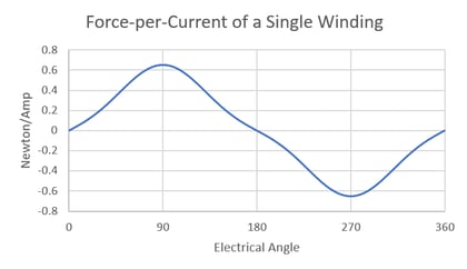
If the amount of force per current of a single winding within a motor is plotted versus the motor position, the resulting graph will typically look something like Figure 1.

The shape of this plot will depend on various aspects of the motor’s construction, but it always follows this general trend of smoothly flowing from optimal to useless and back to optimal, in alternating directions. 

                 Figure 1: Single Winding Force-per-Current Over 360 Degrees of Motor Position

Motor Position and Electrical Angle

In the figure 1 plot, the x-axis measures the ‘electrical angle’ which measures how the rotor/slider of a motor aligns with the stator. The important concept here is that over the full travel of a motor (i.e., 360 degrees of rotation for a rotary motor, or the stroke length of a linear motor), there will often be more than 360 electrical degrees, and the plot above will repeat.

For example, a rotary motor having a 6-pole rotor (3 magnet pairs) would see this plot repeated 3 times in series. This motor would have a total of 1080 electrical degrees over its 360 mechanical degrees of motion.

Linear motors in general have total electrical degrees equal to 360 times the stroke length of the motor divided by ‘pole pitch,’ or twice the distance between adjacent magnets in the slider.

For this discussion, we will concentrate on 360 electrical degrees of motion – noting that commutation will repeat multiple times per revolution or over the total stroke length. And we will ignore the nuances of when a linear motor’s slider retracts into the stator.


Looking at All the Windings in a Stator

Plot of 6 Pole Stator Newton per Amp Map
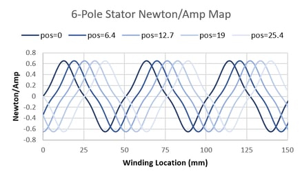
While the figure 1 plot looks at the force-per-current of a single winding at various electrical angles, a similar plot can examine the force-per-current of all the windings in the motor at once, at a fixed electrical angle. As the motor moves (i.e., as the electrical angle changes) this plot will shift left and right.

Figure 2 plots the force-per-current of the stator windings throughout a linear motor. 5 different slider positions are shown to illustrate that as the slider moves, the force-per-current of each of the windings in the stator changes. This linear motor has a slider pole pitch of 50.8 mm and the stator has 6 poles, which implies the stator is 6 x 50.8 = 152 mm long.
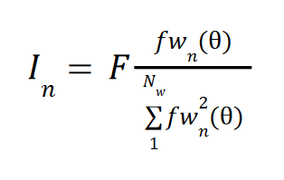
Figure 2: Force-per-Current of All Stator Windings in a 6-Pole
Stator at Various Slider Positions


How Do We Make It Go

The general idea behind commutating a motor is to provide power to the windings that can produce forces efficiently (i.e., those having high force-per-amp magnitude), and not provide power to any useless windings (i.e., those having zero force-per-amp). As the motor moves, the windings that should and should not get power change with it.
 

Ideal Control

What does perfect commutation of a motor look like? This is a problem in which the required force is achieved, while the power losses from heat are minimized. Power loss in nth the winding is found with
 
Equation 1

Equation 1

where In is the winding current, and Rn is the winding resistance. Force generation from the nth winding is found with
 
Equation 2

Equation 2

Where In is again the winding current, and fwn(θ) is the winding’s force-per-amp – which is a function of the motor electrical angle θ (see figure 1 for an example). Power loss P and Force F for a motor with Nw windings are then
 
Equation 3

Equation 3

Equation 4

Equation 4

An important concept in these equations is that force in a winding is linearly proportional to current, while power losses are exponentially proportional to current. The consequence is that it is important to use every winding in the motor that can produce force, and not simply drive the most efficient ones. This is seen with the following example:

Example 1: Optimal Driving of a Two Winding Motor.

Consider a motor with two windings. Both windings have a resistance of 1 ohm. At a particular electrical angle, one motor winding has a force-per-amp of 2 N/A, while the second winding has a force-per-amp of -1 N/A. How can 4 N output be reached?

One intuition might be to use the more efficient winding only: 2 amps into the first winding, 0 current into the second. This solution produces 4 N force at a cost of 4 Watts.

However, the optimal solution is to use 1.6 amps in the first winding, producing 3.2 N of force at a cost of 2.56 Watts, and -0.8 amps in the second winding, producing 0.8 N of force at a cost of 0.64 Watts. This solution produces the 4 N of force at a cost of 3.2 Watts.

While the above is just a simplified example, some math (not shown here) will find that the optimal way to drive a motor is to provide current to each winding proportional to the total required force and that winding’s force-per-amp value, divided by the sum of the force-per-amp values squared of each winding in the motor…which is a mouthful. In another language, a winding’s ideal current in a motor with Nw windings is found with:


Equation 5

Equation 5


Real Life Control

Why Ideal is Unrealistic

The conventional method of delivering power to a winding is to connect each of its leads to one or two MOSFETS (electrical switches) which can connect and disconnect the winding leads to power. It’s for this reason that windings in a motor cannot be powered individually. Rather, they are grouped into ‘phases’ by series and sometimes parallel connections, and then wired to the motor driver as a group. This means that all the windings within a phase receive the same power.

So, we must therefore abandon perfection and consider the trade-offs of grouping windings together. Some windings within a phase may be ‘useless’ while others in the phase are still able to contribute; or some windings within a phase may produce forces in opposite directions, canceling each other out.


The Use of Phases

Stators are grouped into at least two phases and the number of phases used determines the resolution of control that is had over the windings. Two phases means that half of the windings receive a certain amount of power, and the other half receive another amount. Three phases allow each third of the stator to receive a different amount, and so on.
 
Plot of Newton per Amp of Various Phases
 

Figure 3: Illustrations of Grouping the Stator From Figure 2 Into 2 to 5 Phases

To analyze the effect of using more or fewer phases, we can consider an example stator with evenly distributed windings of equal resistance and the same force-per-current profile, except that each profile is shifted according to the winding’s position in the stator. We can divide this stator into 2, 3, 4, and 5 phases.

There is a property of magnetic fields called ‘superposition’ which provides that the force-per-current of a phase is the sum of the force-per-current of each of the windings within the phase1.

Figure 2 shows the force-per-current of all the windings in a motor (at various electrical angles). Figure 3 illustrates dividing those windings up into 2 to 5 phases. Phase groupings are represented by the colored areas: green is phase 1, blue is phase 2, yellow is phase 3, purple is phase 4, and red is phase 5. The colored regions resemble the graphical representation of an integral, which reflect the property of superposition: a phase’s response is the sum of the windings within it.

Like in Figure 2, as the electrical angle changes, so will the shape of Figure 3. The phase distributions (colored regions) will not move, but their area (and therefore their total force-per-current) will change.

Plot of 2 Phase Destructive Interference
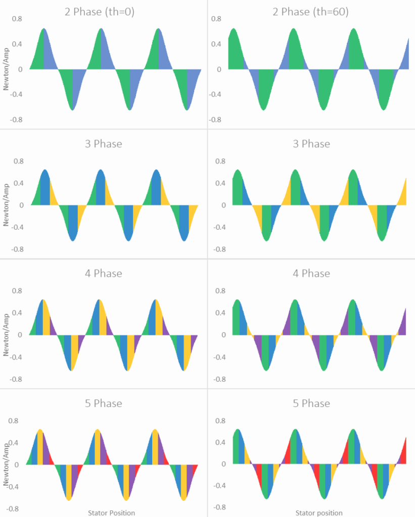
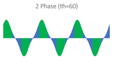
A keen observer might find that the shaded regions would sum to zero, being that there are equal areas above and below the x-axis. And if the adjacent regions were wired without changing polarity, this would be true. Instead, every region is wired with alternating polarity.
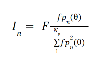


However, when some windings within a single region (a consecutively colored block) are of alternating polarity, these windings will in fact ‘fight’ each other and sum to zero, indicating a waste of power. A clear example of this is seen in Figure 3 – phase 2 (blue) of the 2 phase arrangement suffers from significant losses due to cancellations when the electrical angle is 60 degrees.

Figure 4: Phase 2 (Blue) Regions Suffer From Opposite Polarity Cancellation


1 In fact, this is only true when windings within the phase are connected in series. But while parallel connections in the stator will have implications for the motor driver and required supply voltage, there will be no effect on the motor efficiency, so we can proceed with this assumption for the sake of simplicity.


Ideal Control of Phases

In striving to control the phases in an optimum fashion, the same equation used to find optimal winding current can be applied to phases. Like the individual windings comprising a phase, a phase will have a force-per-current function which depends on the motor positions. We called the force-per-current function of the nth winding fwn(θ), and we can call the force-per-current function of the nth phase fpn(θ). To finding the optimal current for a phase then, we can use:


Equation 6

Equation 6

 
Like the optimal winding current, the derivation of this equation is beyond the scope here, but it proportionally applies current to each winding based on the required force for the motor and the phase’s efficiency compared to the efficiency of all the phases. Equipped with this method of optimally powering a motor of Np phases, we can investigate the advantages of building a motor with additional phases.
 

Improving Efficiency

If we start with the same number of windings, acting on the same permanent magnets, what’s the difference between controlling it in 2, 3, 4, and 5 phases?

To find out, first the force-per-current of the various phases is found at each electrical angle. Next, for each electrical angle, we can find the required power to hit some arbitrary force. Then we can compare the power draw of each phase arrangement and know what is or isn’t to be gained.


Phase Force-per-Current Functions

To find the force-per-current function of each phase, the force-per-current of all the windings comprising that phase are added (making sure to alternate polarity for consecutive poles). For the example stator shown in Figure 2, the following functions are found.
Plots of Force Per Current for 2, 3, 4, and 5 Phase linear motors.
 
Figure 5: Force-per-Current Functions For 2, 3, 4, and 5 Phase Arrangements of the Figure 2 Stator


Getting 100N From Each Arrangement

If we need 100 N out of the motor, it will come with power losses. The amount of loss depends on the resistance of the windings, and how effectively current is applied to the windings. As was shown, using 5 phases provides a finer resolution of control over where power is delivered compared to 2 phases, and this should result in fewer windings fighting each other and more power getting to the more effective windings.

To get the required power at each electrical angle, Equation 6 is applied to find the required currents in each phase. Then total power is found with Equation 1. First though, the phase resistance must be known.

If the assumed total resistance of all the windings in the stator joined in series is 36 ohms, we can use the following resistances for each of the phase arrangements:

 
Number of Phases Phase Resistance
2 18 Ohms
3 12 Ohms
4 9 Ohms
5 7.2 Ohms
 

These numbers simply follow from the assumption that each phase consists of windings joined in series.

The resulting power draw to generate 100 N at each electrical angle is found to be

plot-of-wats-required-to-achieve-100-N-at-each-electrical-angle
Figure 7: Power Required to Achieve 100 N for 2, 3, 4 and 5 Phase Arrangements


How Do Motor Constants Compare?

A motor constant is a measure of a motor’s ability to transform power into force. This is often measured in force-per-square root watt.

In the example from this paper, the discovered Motor constants of each phase arrangement across electrical angles are found to be

motor-constants-of-2-3-4-5-phase-arrangements

Figure 8: Motor Constants of 2, 3, 4, and 5 Phase Arrangements


So What?

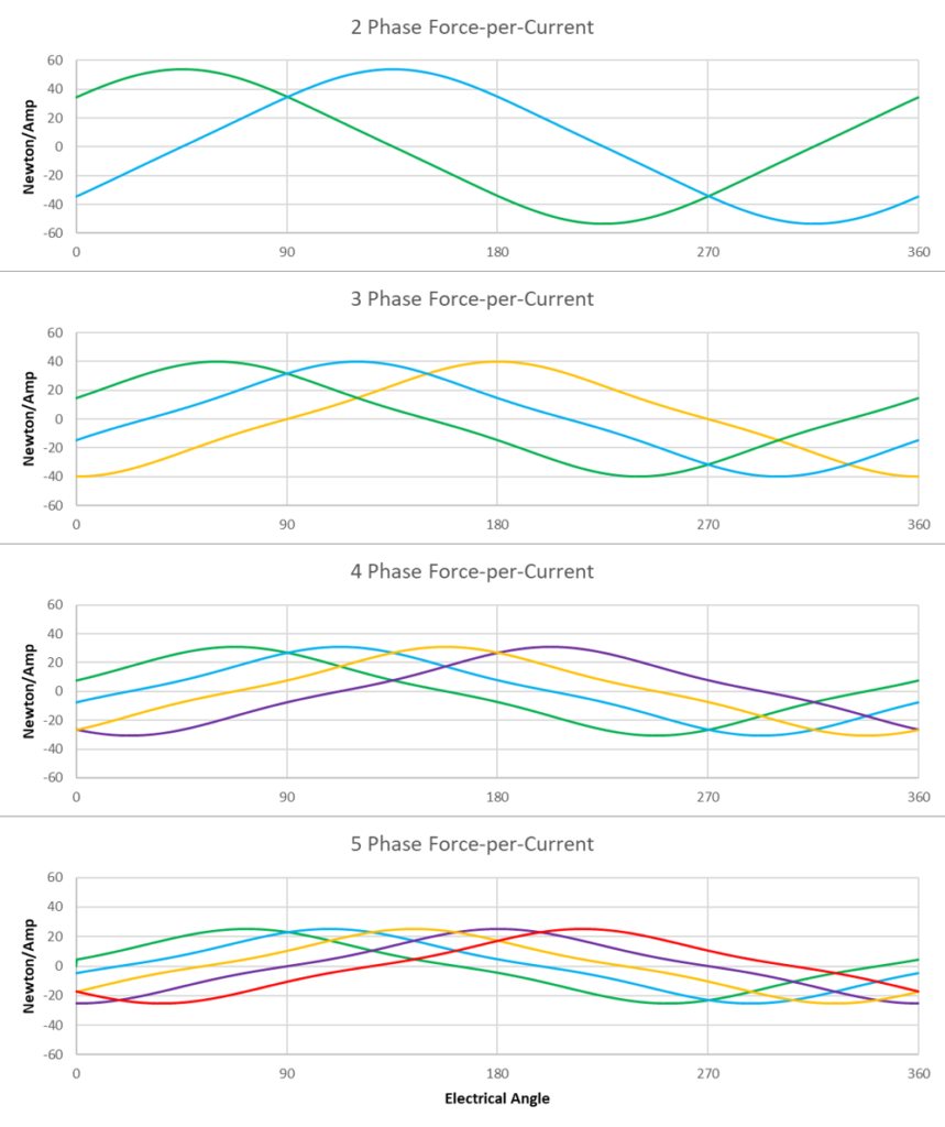
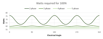
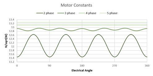
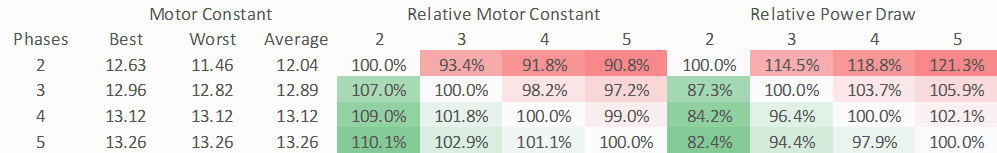
If we start with the same number of windings, acting on the same permanent magnets, we find that controlling the stator in 2, 3, 4, or 5 phases results in a different power cost for the same force output. Specifically:
 
 
Table of Motor Constant Comparison
Figure 9: Comparison of 2, 3, 4, and 5 Phase Power Draw and Motor Constants
 
This means for the same footprint and material, adding or removing phases from a motor design directly and significantly impacts the power efficiency of that motor.
 

Why Use 2 Phase When it Burns 18% More Power Than 4 Phase?

With most industrial motors being wound in 2 or 3 phases, this might be a natural question at this point. Mostly, this comes down to tradition and complexity.
 

Tradition

With less than 200 years of experience making motors, our society is far from arriving at an optimal solution. Engineers are always dealing with new tools arriving and the state-of-the-art evolving.

Initially, commutation was done with mechanical contacts (brushes), and the concept of driving the stator windings with any sort of optimal mathematics was totally out of the question. Fewer phases meant fewer mechanical contacts and fewer failures. Fair enough!

When brushless motors came about, they were essentially wired directly to the power distribution networks which were all 2 or 3 phases. Again, no precise control over phase currents could be had.

When methods of electrical angle detection (e.g., hall sensors and encoders) and motor driver technology advanced to the point that precise current control could be had, designers were encouraged to build 2 and 3 phase compatible systems that could serve the vast number of 2 and 3 phase motor bodies in existence.

Today, a great majority of motor drivers and control software available caters only to 2 and 3 phase motors. 


Complexity

Intelligently controlling a motor to hit peak efficiency requires significant engineering. One needs fast and accurate current controls, fast and accurate electrical angle detection, some knowledge of the force-per-current of the motor in question, and logic which ties everything together with low latency. So, even controlling 2 or 3 phases optimally is a tall order.

When the motor phases and the motor driver are remotely located, as they typically are, each phase requires power leads to be run between the motor and driver. These leads carry significant power, and significant fast voltage transitions that can cause radio wave interference (EMI) which could corrupt nearby sensor lines.

For example, adding 4 more of these lines by moving to 4 phases from 2 phases is not only expensive but also potentially causes other problems.


Why Use 4 Phase When It’s Much More Complicated Than 2 Phase?

Despite the challenges, more reasons are coming up to get the most from electric linear motors. Rising energy prices might incentivize factories to optimize their motors to reduce power consumption. Extending range might incentivize an electric car manufacturer to invest in efficiency gains. Rapidly increasing prices for rare earth metals like Neodymium make squeezing more performance from less material make even more sense.

For information on 4 phase linear motors, check out the Orca™ Series linear motors from Iris Dynamics Ltd. The integrated drivers and advanced control algorithms handle the complexities and provide a good feature set with excellent power efficiency and force density at low voltages.